 Chemical injection or metering pump packages are not a one-size-fits-all product. Most systems are engineered based on specific process and site conditions and are therefore expected to have variations in functionality and design. Nevertheless, just as one would expect to find with a vehicle’s drive train, there are key components that you can also expect to find on virtually any chemical injection package. Below is a list of those key components and an overview of the purpose and basic function of each device:
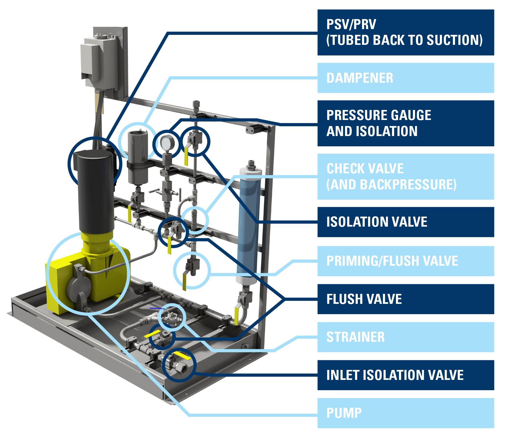
1) Strainer
- Used to prevent particulate from entering and becoming lodged in components with small orifices; primarily the check valves located in the head of the metering pump.
- Even though the chemical being provided is likely to be clean, small contaminates can still enter the system during commissioning and operation when supply connections, hoses, or fittings may not be protected.
- There is a high chance of contaminates entering the system when totes are being swapped out and hoses are being disconnected and swapped. Tanks that have been in use for a long time without being cleaned, or bulk tanks that have large vents or openings may allow particles to enter the system as well. Different mesh sizes and types of strainers such as “Y” and “Basket” can be selected based on each particular application.
2) Pulsation Dampener
- Used to dampen or absorb the energy from the pump discharge stroke. The dampener will discharge the stored energy downstream into the system while the pump is in its suction stroke position. Because the pulse of fluid out of the pump is being discharged or spread out over a longer period of time (versus a quick pulse or high flow and then no pulse or no flow periods), this enables the system to use a smaller diameter and/or longer discharge line and/or higher viscosity than could be used without the dampener in place.
- Eliminates the possible hammering or periods of higher pressure that the pump and system might encounter. If these spikes exceed rated pressures for even short periods of time, catastrophic damage could occur to the pump internals. This could result in rupture or decreased life of diaphragms, motor, and pump gears.
- If the pressure spikes are too close in pressure to the setpoint of the PSV/PRV, it could be possible for a small amount of fluid to be re-routed through the PSV/PRV rather than downstream to the injection point as intended. The pulsation dampener reduces these pressure spikes and thus decreases the likelihood that the overall system pressure will get close to the setpoint of the PSV/PRV ensuring that the system is more stable overall, and that all the fluid intended to go downstream goes to the injection point.
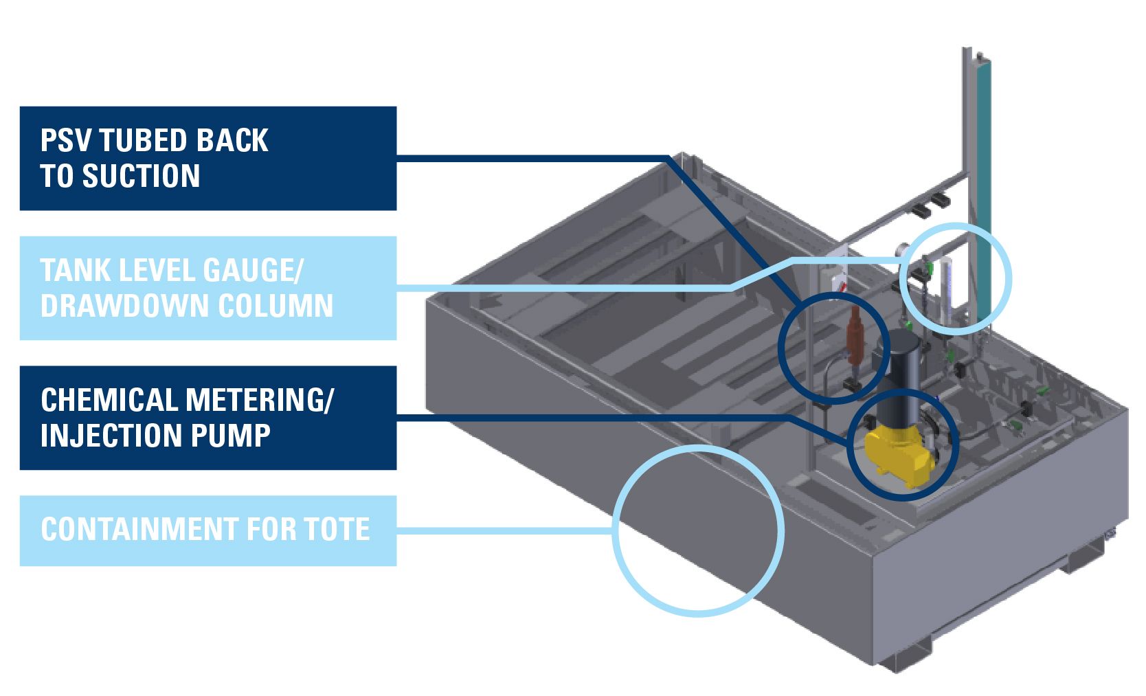
3) PRV/PSV
- A Pressure Relief Valve (PRV) or Pressure Safety Valve (PSV) is used on a chemical injection system to prevent the pressure downstream of the pump from exceeding a pre-set limit.
- This device is primarily used to prevent positive displacement pumps (reciprocating piston, diaphragm or other types of metering pumps) from exceeding the system’s maximum design pressure. Many systems are designed to use pumps that could exceed the design pressure of the piping, tubing, and hose and components, if the system were to be blocked in (fluid prevented from flowing into the injection point).
- A PRV and a PSV are both considered pressure relieving type valves, but the PSV typically describes a device used within an ASME registered pressure system (piping or vessels). It functions by “popping” open to provide discrete overpressure protection. The PRV normally refers to a device that has a more gradual opening or proportional overpressure protection.
- PSV’s/PRV’s should be sized to have enough flow relief capacity to meet the maximum designed flow rate. They should have an approximate overpressure margin of 20% to accommodate pressure spikes in the system when running at maximum design capacity.
- Hydraulic diaphragm pumps will typically incorporate an internal PRV in the design of the pump but this is not to be relied upon for protecting the system or the pump under longer periods of operation. If the pump’s internal PRV is activated and bypassing for extended periods of time, the oil being recycled through this small opening will build up heat to the point of damaging the pump internals. These valves are typically designed for very short periods of activation to prevent instant damage to the pump and possible unsafe conditions for operators in the area. The use of an external PRV or PSV is a necessity for a safe system when using any type of positive displacement pump. The pump’s internal PRV’s are typically set about 15% above the set pressure of the external PSV/PRV on the package so that the external PRV/PSV operates before the internal PRV is required.
Pro Tip: Size and select the PRV or PSV properly to prevent any chance of the system pressure exceeding the pressure rating of any one component used within the system. This process must take into account all possible sources of pressure spikes or build-up due to excess back pressures created from downstream components, piping, temperature changes, chemical viscosity and chemical reactions from pulsating or reciprocating pumps.
4) Pressure gauge and Isolator
- The pressure gauge is very useful in a chemical injection system to help troubleshoot and determine when a pump or another component is not operating to specification.
- For safety reasons, a pressure gauge is highly recommended so that you can visually see when the system pressure has been released before removing any components for service. The isolator is a diaphragm which can be made of a variety of materials and provides a barrier between the fluid and the pressure gauge. This allows the use of a gauge that may not normally (without the use of the isolator) be suitable for service in the system due to either incompatible materials or a design that can become lodged with chemical or other material over time.

5) Priming/flush valve
- It is good design practice to include a suction flush valve upstream of the pump and other suction components and another valve for priming or flushing downstream of the pump and discharge components. This allows the user to connect a water or suitable flush fluid line into the suction of the system to push and flush the chemical through the pump and other components and out through the discharge flush valve into a suitable waste collection vessel before opening the system for servicing.
- The discharge priming/flush valve is also used when starting up the pump dry. Opening the flush/priming valve downstream of the pump will allow the pump to operate into atmospheric conditions and help remove gas from the system. Without this valve, and if there is a source of backpressure downstream, the pump may only compress and de-compress the gas with each cycle and may not be able to overcome the backpressure. This would result in the system being unable to prime or move any liquid through the system.
6) Check valve or back pressure valve
- Check valve or back pressure valves prevent any downstream pressure from flowing back through the pump checks and into the chemical tank. The pump has check valves that will help but they are not usually spring-loaded and therefore will bypass fluid over time.
- They also provide repeatable pump volumes. Most metering pumps require around 15 to 30 psi of backpressure to assist with the check valves operating optimally. Flow rates can vary significantly on some pumps if some back pressure is not applied.
- This device also prevents syphoning or gravity/free flow of chemical. If the pump discharge line is injecting into a process that is at a pressure slightly below the head pressure provided by the tank/supply fluid and the pump check valves do not have springs, fluid can flow freely through the pump (from suction to discharge direction) and into the injection point. Without a source of back pressure in the system, a full tank of chemical that is at a slightly higher elevation than an atmospheric injection point could completely drain out through the pump, even with the pump turned off.
Pro Tip: A spring-loaded check valve or back pressure valve should be selected with the appropriate amount of spring tension and back pressure to prevent the supply pressure from exceeding the total amount of back pressure in the system.
7) Bleed valve and isolation valve
- A bleed valve or isolation valve is used at the discharge of a chemical injection package where the discharge line to the injection point would be connected.
- The isolation valve does just that, it “isolates” the pump package from the rest of the downstream piping/process system so that the package can be worked on safely without risk of process fluid coming back into the pump package while components are removed or being serviced. It also prevents having to drain the full injection line before working on the pump package.
- The bleed valve would be tee’d into the discharge line of the pump package just upstream of the isolation valve but downstream of the check or backpressure valve. This bleed valve will allow you to bleed off the pressure that is trapped between the check valve and the isolation valve after closing the isolation valve and before opening the line or removing the check valve for service.
Pro Tip: To ensure proper operation, it is very important to consider the chemical viscosity, flow rate and pressure when selecting the components for the package. Components are manufactured from a large variety of materials and it is necessary to confirm that the chemistry being used in the package will be compatible with all wetted materials and elastomers in each component.